![]()
An international standard for the exchange of engineering analysis data will be published this month (August 2001). The standard is ISO 10303 part 209 'Composite and metallic structural analysis and related design'. This is a Application Protocol within the STEP (Standard for Exchange of Product data) family of standards. AP 209 will enable:
AP 209 covers:
 |
AP 209 has been steered through a lengthy standardisation process by the project leader Keith Hunten, P.E., a senior staff engineer with Lockheed Martin Aeronautics in Fort Worth, Texas. Keith says
The configuration management within the standard supports the design and analysis practice within Lockheed Martin, where the rapid evolution of complex products requires the simultaneous tracking of design versions and analysis versions. The ability to link analysis with design data encompasses all the functionality of existing systems, and defines capabilities that we would like future systems to address.
AP 209 implementation is being pioneered by the Engineering Analysis team within PDES Inc.. PDES Inc. is a consortium of aerospace, automotive, and shipbuilding companies in USA, UK and France that helps is members achieve business benefits from the use of STEP. The AP 209 implementation pilot involves Boeing, Rolls-Royce, Electric Boat, Lockheed Martin, NIST, Theorem Solutions and MSC Software. The companies are working together to ensure the availability of high quality interfaces between AP 209 and existing CAD and FEA systems.
Steve Gordon, principal engineer at Electric Boat, says
Electric Boat is moving away from traditional practice, where designers designed and analysts did calculations, towards the use of analysis at each stage in the design process starting with conceptual design. AP 209 is an enabler for improved CAD-CAE integration. We are interested in the ability of the standard to associate analysis information, such as thickness with shells and section properties with stiffeners, directly with both the nominal design and idealized geometry models.
MSC Software has contributed to the development of AP 209, providing software expertise, a 'reality check' to the standardisation work, and commercially available translators. A web browser for AP 209 files is available free of charge from MSC Software. Tom Mack of MSC Software says
AP 209 is an opportunity for MSC - not a threat. Our business is to provide design and analysis solutions - not just to ship copies of PATRAN and NASTRAN. The adoption of AP 209 means that our software can be part of the customers business practice - as and when the customer requires, on the customer's computer or over the web on ours.
Rolls-Royce has been one of the pioneers of the STEP standard and has used it for day to day exchange of geometric information with Boeing during the past six years. Rolls-Royce is now working with Boeing to test the use AP 209 for the exchange of 'whole engine models'. These models are used to investigate the behaviour of the engine, pylon and wing as a complete assembly.
Derek Pashley, corporate mechanical methods specialist at Rolls-Royce, says
AP 209 has at least two roles for us. Firstly, we exchange data with the aeroplane builders. At present they use the same systems as us so native formats work, but eventually analysis systems change and it is useful to have flexibility. Secondly, we need to retain analysis data used for certification until after the last engine to that design has stopped flying. This is fifty years or more - much longer than the lifetime of any analysis system. The use of standards is the best way to ensure that the data will be understood when it is retrieved.
NAFEMS began twenty years ago at time of crisis within the engineering analysis community. Finite element analysis codes were being used for safety critical applications, but there were no standard tests available to validate the accuracy of the codes. An early deliverable of NAFEMS was the set of 'NAFEMS benchmarks'. Over the years, these benchmarks have been extended from linear elastic analysis to cover material non-linearity, creep and finite element pre-processors.
There are many information exchanges during the analysis process - shape information from CAD system to finite element pre-processor; finite element analysis model information from pre-processor to analysis code; and finite element results from analysis code to post-processor. The post-processor may be concerned solely with visualisation, but may also carry out detailed design, design optimisation or code checking activities.
AP 209 can standardise each of these interfaces. But, there is the possibility that miss-interpretation of AP 209 anywhere within the process will lead to plausible but wrong answers. The are many potential problems - element axes systems can be incorrectly applied, loads can be applied to the wrong element faces, unit conversions can be incorrect (AP 209 is explicit about units!). AP 209 does not make these problems worse. Instead, the standardisation of the interfaces makes it easier to validate the complete process.
As a first stage in the creation of a validation set for AP 209, NAFEMS is working with the PDES Inc. Engineering Analysis team to publish the existing NAFEMS benchmarks as AP 209 files. These benchmarks have known correct answers, so they can be run through all or part of the analysis process to validate it.
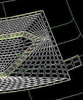
PDES Inc. and NAFEMS are also producing benchmarks of industrial complexity, which will test the complete range of features within AP 209 and will validate system performance. The first of these industrial benchmarks is a whole engine model provided by The Boeing Company, and shown in the figure.
AP 209 is one of the STEP family of standards which embrace all aspects of product data. Major components of the family are:
The scope of the standards within the STEP family reflects the major input to STEP from the aerospace, automotive, electrical, process plant and shipbuilding industries.
The use of engineering analysis in industry continues to develop, with major new areas being:
Standards are moving forward to address these areas. On the one hand, standards inevitably lag behind the cutting edge in terms of analysis methods. On the other hand, standards are developed by users, not vendors, and so have a broad perspective concerning the integration of analysis with the rest of the business process. Interfaces between different disciplines are a priority for standardisation.
Engineering analysis standards developed along side AP 209 are:
The Engineering Analysis Core Model is a packaging of these components and AP 209 into a single into a modular architecture. This will support the 'plug and play' combination of components, enabling different analysis disciplines and analysis methods to be used together as required.
This article was written by David Leal of CAESAR Systems. David is a member of the NAFEMS CAD/FE Working Group, and represents NAFEMS on ISO committee TC184/SC4, which is responsible for STEP.